Ferrites
Isolators and circulators are technologically important components used in the construction of many millimetre wave systems. These can either be waveguide or free-space (quasi-optical) devices, but in either case they employ ferrite material to produce their non-reciprocal behaviour.
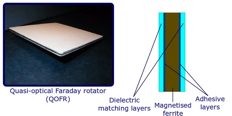
Over the past 30 years, our group has developed considerable expertise in the construction of high performance quasi-optical Faraday rotators (QOFRs) for use in millimetre wave quasi-optical systems for a wide variety of applications.
In a quasi-optical system, isolators and circulators are constructed using QOFRs, wire grid polarisers and quasi-optical loads. When the millimetre wave beam passes through the QOFR, the polarisation plane of the beam is rotated by 45°.
Isolators, as their name suggests, are used to isolate parts of a larger system and allow the low-loss transmission of signals in one direction whilst preventing the unwanted return of any reflected signals in the opposite direction.
Circulators are used for signal routing within larger systems, for example in a monostatic radar system where a signal needs to pass from the transmitter to an antenna for transmission to the scene and where the signal which returns to the antenna from the scene then needs to be routed to the receiver for detection. In this case the circulator ensures that the transmitted signal does not pass directly to the receiver and also that the returning signal is routed correctly to the receiver rather than back to the transmitter.
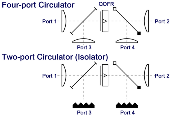
In the diagram above, the polarisation at port 1 is vertical (0°). Passing through the QOFR to port 2, the polarisation is rotated to +45°. A signal from port 2 at +45° which passes back through the QOFR will be further rotated by another 45° due to the non-reciprocal behaviour of the QOFR. The beam will now be horizontally polarised (90°) and so will reflect from the wire grid polariser to port 3. A horizontally polarised signal from port 3 passing through the QOFR will then be further rotated by 45° on passing the QOFR and will now be polarised at -45° so will reflect from the polariser grid and pass to port 4. Finally, a signal from port 4 polarised at -45° passing back through the QOFR will be rotated by a further 45° and so will now be back to 0° and so return to port 1. When constructing an isolator, or if making a 3 port circulator, the unused ports are terminated with quasi-optical loads.
The state-of-the-art HiPER spectrometer contains five QOFRs in order to prevent reflections within the system and achieve spectacularly low system dead time. (Dead time is the length of time that must be waited after the transmission of high powered pulses into the system for any echoes of those pulses to have decayed away sufficiently that it is safe to open the receiver and thus be able to detect the tiny signals which are emitted by the sample).
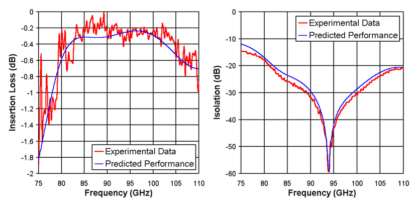
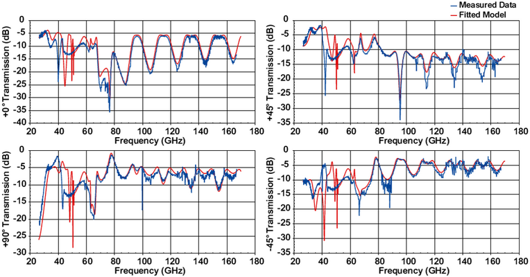
In order to construct the best possible QOFRs it is necessary to characterise the ferrite material, selecting the material with the lowest losses and optimising the thickness of the ferrite material used to provide the required 45° polarisation rotation per pass at the desired operating frequency. The magnetised ferrite tiles are measured in transmission and reflection at defined polarisation angles and a model is fitted to these data to determine the dielectric and magnetic properties for each tile.
These fitted parameters are then passed to a second model along with parameters for dielectric matching materials, used to make anti-reflection coatings for the QOFRs, and so the final QOFR designs can then be optimised for each specific application in terms of centre frequency, operational bandwidth and return loss.